School of Engineering and Sciences
Department of Electrical and Electronics Engineering


In this experiment, the main aim is to verify Kirchhoff's voltage Law .
Kirchhoff’s Voltage Law states that the algebraic sum of the
voltages (or voltage drops) in any closed path of a network that
is transverse in a single direction is zero.

In this experiment, the main aim is to verify Kirchhoff's current Law.
Kirchhoff’s current Law states that the algebraic sum of all the currents at any node point or a junction of a circuit is zero.

In this experiment, the main aim to verify Ohm's law.
Ohm's law states that the current through a conductor between two points is directly proportional to the voltage across the two points.

This setup is designed to study the Thevenin’s, Norton’s, Superposition theorem.
1. To study the Thevenin's Theorem & determine the values of VTH & RTH for the different values of Vi.
2. To study the Norton's Theorem & determine the values of Norton's Current IN & Norton's resistance RTH for the different values of Vi.
3. To study the Superposition Theorem & determine the values of Current & Voltage across R2 for the different values of V1 & V2.

This setup is designed to study the Maximum Power Transfer theorem, Reciprocity theorem & Superposition theorem.
1. To study the maximum power transfer theorem & determine the value of current, voltage, source impedance & power delivered to resistive load for the differnt values of applied DC input Vi.
2. To study & verify Reciprocity Theorem.
3. To study & verify Superposition Theorem.

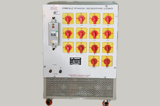
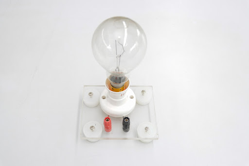
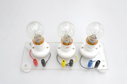
In this experiment, the main aim is to study and plot the following V-I Characteristics of Tungsten Filament Lamp.

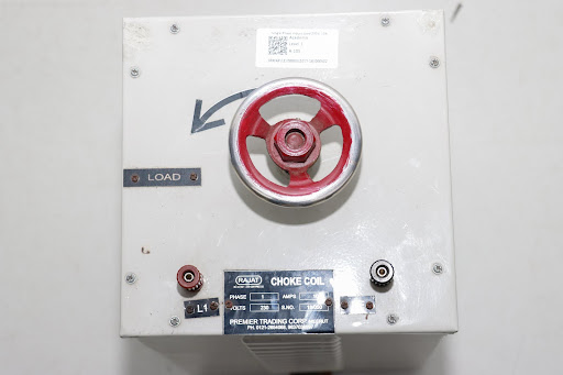
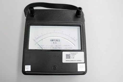
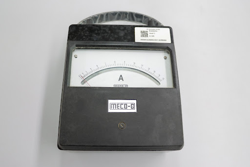
In this experiment, the main aim is to measure single-phase power by using three ammeter method.
The circuit diagram of measuring single phase power with the use of three ammeters is shown in the figure.
In this method, a non-inductive resistance R is connected across the inductive load with three ammeters arrangement. P = (l12-l22-l32) R/2.

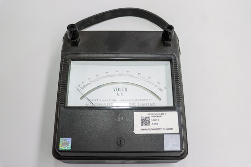
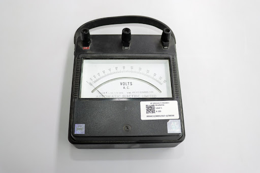
In this experiment, the main aim is to measure single-phase power by using three voltmeter method.
The power in a single-phase circuit can be measured using three voltmeters and the connection circuit for this method is shown in the figure.
Here the load is inductive, V1, V2 and V3 are voltmeters and R is a purely non-inductive resistance, which is connected in series with the circuit. Therefore, Power P = (V12-V22-V32)/2R.

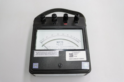
In this experiment, the main aim is to measure three-phase power by two wattmeter method.
Two wattmeter method can be employed to measure the power in a 3 phase, three-wire star or delta connected the balanced or unbalanced load.
In this circuit, the measure of three phase power is used in a star or balanced load.

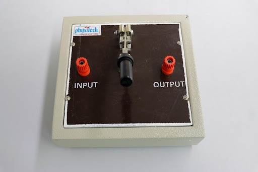
Single pole single throw switch 32 amp
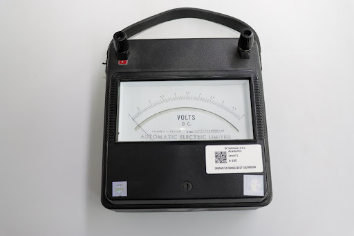
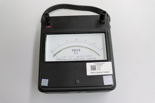
Dc voltmeter 0 – 10V
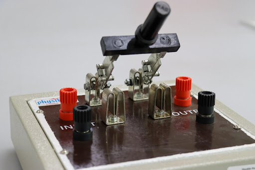
Double pole single throw switch 32 amp
I. Compact and user friendly learning platforms to gain invaluable knowledge about order and type of Control System.
II. Square wave, Ramp wave, Parabolic wave, Unit step signal and variable DC supply are provided on board as standard inputs.
III. On board Resistance, Capacitor and Inductor banks for studying different combination for the order of a system are also available.

I. Helps the user to gain invaluable practical experience of the principles and application of DC motor position control.
II. Helps in understanding the concept of Robot controls.

I. Introduce students the operation and control of stepper motor effectively.
II. It helps the student in understanding half and full step angle of stepper motor with visual indication of the coil excitation process.
III. It has a provision for connecting the motor with an external controller designed by students.

I. Students can study two-position mode as ON/OFF Controller and continuous Controller modes as Proportional (P), Integral (I), Derivative (D), PI, PD and PID control modes.
II. First order system and second order system in open loop and closed loop system.

I. Helps the user to gain invaluable practical experience of the principles and application of Leading Lagging of a signal applied to any active network.
II. Helpful to study Lead, Lag and Lag-Lead in the networks as a filter, analysis through Bode plots and compensation of the same.

I. Exposes students to the fundamentals of Control System.
II. Studies include how one device can be used manage, command, direct or regulate the behavior of other system Open Loop & Closed Loop Control.
III. Nvis 3000A (as shown in below figure) has various parts like Temperature Sensor, Light Sensor, DC Motor, Servo Motor, LED lamps, IR Sensor, Relay SPST, and Relay DPDT; De-bounce switch, LED Bar, Buzzer etc. which can be used for study of Control system.
IV. Nvis 630 DAQ is very useful for sensing and controlling analog and digital signals of any process.
V. It makes easy and interesting to interface real world signals with PC through USB bus.


1. Analog Input
2. Analog Output
3. Fixed User Power Supplies
4. Digital I/O
5. User peripherals
6. Digital ground
7. Central build area (breadboard)
8. Fixed User Power Supplies LEDs


1.Brushed DC motor with 24 pulse/revolution photo microsensor
2.Current sense for brushed DC motor
3.Linear power amplifier
4.PWM power amplifier
5.Brushless DC motor with integrated Hall effect sensors
6.48 step unipolar stepper motor
7.Servo motor


1.Direct-drive brushed DC motor
2.512 count encoder mounted on the motor and on the pendulum arm
3.Built in deterministic PWM amplifier mapped to theoretical motor models
4.DC motor current sense


1.Variable linear DC power supply
2.Three-phase AC generator assembly
3.Three-phase rectifier with selectable capacitance
4.Buck and boost switched-mode DC power supply circuits
5.Single phase inverter circuit with transformer and resistive AC load
6.Adjustable DC current sink
This setup is designed to study the transmission line parameters (A,B,C,D) of a transmission line model. This set up consists of : AC transmission Line Model, meter set up.

This Dc distribution system Trainer is specially designed to study the various type of dc distribution network system.
Study of Radial Distribution network.
Study of Ring Main Distribution network.
Study of Inter Connected system.

This set up is designed to study the measurement procedure of Sequence impedance (Positive, negative, Zero), and study the measurement of fault current by simulating various types of faults (LG,LL,LLG,LLLG etc.) under low field voltage.
Measurement of Sequence Impedance of Alternator.
Measurement of Synchronous Impedance of Alternator.
Measurement of Fault Current for various types of faults (LG,LL,LLG,LLLG etc.).

This set up is designed to study the measurement of Power angle of an alternator. This set up consists of 3 Phase Alternator with prime mover set up & Control Panel with Fault simulation switches.
Measurement of POWER ANGLE characteristics of alternator with infinite bus bar.

This trainer set up is designed to study the measurement procedure of ‘Positive , Negative & Zero sequence impedance’ of 3phase transformer and study the measurement of fault current by simulating various types of faults (LG,LL,LLG,LLLG etc.)under low field voltage.
Measurement of Sequence Impedance of transformer.
Measurement of Fault Current for various types of faults (LG,LL,LLG,LLLG etc.).

This trainer set up is designed to study the measurement procedure of ‘Positive , Negative & Zero sequence impedance’ of 3phase transmission line and study the measurement of fault current by simulating various types of faults (LG,LL,LLG,LLLG etc.)under low field voltage.
Measurement of Sequence Impedance of transmission lines.
Measurement of Fault Current for various types of faults (LG,LL,LLG,LLLG etc.).
Study of Relay Operation.

This trainer is designed to study the V-I characteristics (STATIC characteristics) of SCR, TRIAC, MOSFET and IGBT. This trainer consists one number of SCR(TYN 612), TRAIC(BTA12), MOSFET(IRF840) and IGBT(IRGBS30S) with heat sinks.

This power module is designed to study the single phase half & fully controlled bridge converter with R, RL and RLE LOAD. This module is designed by using SCR & DIODE for AC-DC Controlled Converter applications. This power module can be used for DC Motor open loop & closed loop speed control application .

This module is designed to study the 3 phase half & fully controlled converter with R, RL and RLE LOAD, Ac Voltage regulator power circuit. This power module can also be used for DC Motor open loop & closed loop speed control application.

This set up is designed to study the BUCK switch mode converter circuits. This set up consists of PWM Controller, MOSFET Power circuit & DC Power supply.
Study of DC-DC Buck Converter.

This set up is designed to study the BOOST switch mode converter circuits. This set up consists of PWM Controller, MOSFET Power circuit & DC Power supply.
Study of DC-DC Boost Converter.

This module is designed to study the single phase dual converter with R, RL loads. This module is designed by using SCRs for combination of rectifier (AC to DC) and inverter (DC to AC) applications.
Study of Single phase fully controlled full bridge converter with R & RL loads.

This trainer is designed to study the working of IGBT based DC-AC inverter ( single phase & 3 phase) using various PWM techniques. It consists of IGBT PWM Controller & 3 Phase IGBT Power Circuit, RL Load & DC Power supply.

This trainer is designed to study the working of IGBT based DC-AC inverter ( single phase & 3 phase) using various PWM techniques. It consists of IGBT PWM Controller & 3 Phase IGBT Power Circuit, RL Load & DC Power supply.
Study of 3-phase PWM & non PWM Inverter.
Study of PMDC back to back coupled motor control.
Study of Speed Control (Open Loop/Closed Loop) of PMDC Motor using IGBT Chopper.
Study of Four quadrant operation of dc motor using IGBT Chopper.

This setup designed to study the working principle of single-phase step-down cyclo-converter (Mid Point type). This setup consists of Single phase cyclo converter firing circuit and SCR power circuit.
Study of Single Phase step-down midpoint type cycloconverter.


")